Special products
CAISA carries out 2 processes highly differentiated from pressure vessel and tank manufacture:
-
SLUDGE DRYING SYSTEM BY MEANS OF KEY TECHNOLOGY
THE SYSTEM
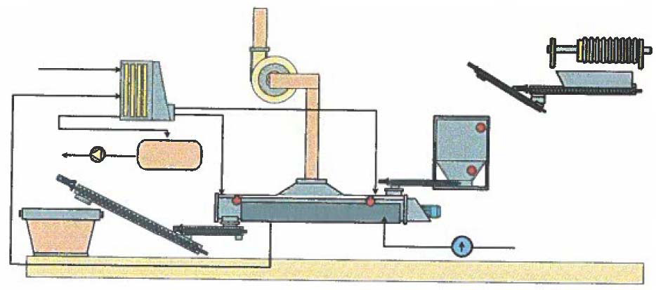
CLAV technology is an indirect, low-speed, thermal drying system, designed for continuous thermal dehydration (although also useful for alternate) for wet sludge, so as to decrease the final mass to be sent to the dump, reducing (and eliminating if necessary) the generation of leachates, and consequently, costs to eliminate the leftover waste are reduced.
It was initially used to physical-chemical, biological or mixed treatment systems, with initial implementation for textile, paper, chemical, metallurgical, food, pharmaceutical, tannery, slaughterhouse, waste collection and urban treatment system industries. Over time, the versatility of the system was observed and it was extended to drying any material that may be dehydrated, beginning with a wet product with sludge or compact paste morphology which, upon being dehydrated by means of this system, turns into gravel or dust.
The thermal dryer with CLAV technology dehydrates products with initial humidity between 90-65%, bringing them down to humidity below 25%, and can reach 2-3% humidity if necessary, depending on each product and the end humidity required by the treatment.
TECHNICAL CHARACTERISTICS
HEAT INPUT METHOD as means of heat input, the system developed may use pressurised water vapour, thermal oil or superheated water. None of these methods enter into contact with the product to be dehydrated, the method does not surpass 170º C, and the temperature of the product to be dehydrated is kept between 95 and 105º C. The advantage of this low temperature is an absence of atmospheric emissions, as opposed to emissions produced at greater temperatures.
The principle of operation is the combination of an effective means of transportation with the transmission of heat provided by the thermal method. The great advantage is that the latent enthalpy of the thermal method is taken advantage of to the maximum, and consumption of the thermal method is limited and known. This type of CLAV technology dryer is a pressure vessel approved by Industrial Safety services and calculated according to the AD-MERKBLÄTER code for St37.2 carbon steel, constructed by CAISA Constructora Auxiliar de Ingeniería, a manufacturer approved for Pressure Apparatuses. Welding procedures, as well as the welders, are also approved.

METHOD OF TRANSPORTATION
Inside of the dryer, there is a specially designed transporter to pass pasty products through. Additionally, the design is such that as the product loses water, it is chopped.
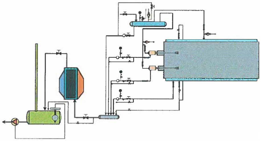
The transporter's size is optimised to guarantee proper passage of the product, given that the product's humidity and rheological characteristics vary within the dryer. As a result, the dryer optimally combines the passage system with the thermal exchanger, in such a fashion that the very thermal exchange circuit is an integral part of the passage system. The thermal energy circulates inside of the means of transportation, turning its surfaces into heat exchange areas, as well as the frame, which also acts as a heat exchange surface. If the thermal method is vapour, a purge is designed to evacuate possible condensations of the thermal method. The product to dry enters into the dryer through a collection hopper with an auger that brings the material inside of the drying, turning an alternate input into a continuous input within the dryer. For internal transportation within the dyer, motors are used that generate a qualitatively low rotation speed (around 1 r.p.m.) but with elevated torque. This means advantages are generated, such as greater thermal exchange time, transportation strength and low electrical consumption for motors. GENERAL STIPULATIONS In complementary fashion, and in many cases absolutely necessary, the dryer has a vacuum for vapours coming about from dehydrating the product, which brings them to a carbon filter or a scrubber (according to the vapour's characteristics) before releasing them into the atmosphere, thereby guaranteeing minimum environmental impact in the dryer area. In each case, the most appropriate system should be studied and applied, taking possible solids, vapours, contaminants or bad odours into account.
The effective hourly power consumption is around 90% of installed power. If the product's drying requires more than one electrical power module, it will be conditioned by the dryer's end size or by the number of modules of which it is made.
 The equipment must be connected to the general line of the plant's thermal method (company) or if not available (there is none), a small gas, gas-oil or biomass boiler will be installed to supply the drying system. There will be input and output plumbing. The construction material will be in accordance with the product to be dehydrated, normally carbon steel, and especially sensitive parts made of stainless steel. If the characteristics of the product to be dehydrated are especially corrosive, the construction will be made with more rust-resistant materials. The entire drying system is controlled with an electric panel with a control and manoeuvring panel and protections located adjacent to the dryer.
 -
BILGE AND WASTE WATER COLLECTION EQUIPMENT
TECHNICAL BID
In order to provide service to all users of the new port regarding collection of bilge and grey water, a collection system has been designed that operates by means of a vacuum network. In other words, the bilge and grey water is suctioned from yachts through a vacuum in segregated fashion, and the bilge water is stored in a tank for decantation and later evacuation. The grey water is directly dumped into the public sewage system.
The installation is segregated into different equipment to independently provide service and also adapt to the construction phases in remodelling the new port. Given that bilge water must be treated differently than grey water, equipment is installed to collect bilge water with a connection at the petrol station, and two different pieces of equipment are installed to collect grey water: a first piece of equipment to collect grey water from the Barceloneta, Rellotge and Pescadors docks, which also includes the Recepción and Club Lounge buildings, and a connection at the petrol station (next to the bilge water) and a second piece of equipment that provides service to the entire España dock. Bilge water is collected through a vacuum installation. This installation is made up of a Treatment and Vacuum Centre (TVC) located in the machine room (located behind the new lorries located in front of the museum) which, with a vacuum pump, create a vacuum in the entire circuit, and by opening or closing a vacuum valve located in the WCC (Waste Collection Centre) in the petrol station, suction bilge water. (See attached schematic, fig. 1)
El TVC is made up of:
- A tank that stores bilge water so that they can decant, thereby segregating hydrocarbons from the water and thereby allowing to dump clean water into the sewage system and bring hydrocarbons to a controlled dumping site.
- A vacuum pump that creates a vacuum in the entire closed circuit and that is mechanically activated upon opening the vacuum valve located in the WCC.
- A small 100 litre Stainless steel tank and a submerged centrifugal pump to dump the segregated water into the sewage system.
- Connection accessories, valves and other elements necessary for the proper operation and control of the installation.
- Optionally, a pump may be installed to propel hydrocarbons to a collection container or a transportation lorry to a controlled dumping site.
El WCC is made up of:
- A reel to wind the hose
- Hose and lances for suctioning
- EVV (Evacuation vaccum valve)

GREY WATER COLLECTION
Grey water will be evacuated by means of two independent pieces of equipment (one per installation phase), but with the same typology. These pieces of equipment operate in a similar fashion to the bilge water evacuation equipment, as they both operate by means of a vacuum.
Each one of these two pieces of equipment are made up of a WWVE (Waste Water Vacuum Equipment), located in the machinery room. In the case of equipment for the España dock, in addition to the WWVE, there are three connection turrets with a EVV on each one of them. In the case of the equipment for the Barceloneta, Rellotge and Pescadors docks, there are three turrets with one EVV on each one of them, three connections at the Recepción building with three EVVs, one connection at the Club Lounge building with one EVV and one last connection at the petrol station located within the bilge water WCC (of note is that although it is located in the same WCC as the bilge water, it is totally segregated). (See attached schematic, fig. 2)
Each one of the WWVE are made up of:
- A STAINLESS intermediate storage tank for before dumping into the sewage system
- A vacuum pump that creates a vacuum in the entire closed circuit and that is mechanically activated upon opening any of the valves located in its circuit.
- Two centrifugal pumps for dumping by propulsion to the public sewage system
- Connection accessories, valves and other elements necessary for the proper operation and control of the installation.n.
- Optionally, and given that the two-phase WWVEs are interconnected, it is possible to install a second vacuum pump in the first execution phase.
It should be noted that all connection points are joined to the TVC or WWVE, respectively, by means of polyethylene, high-density pipes with different diameters, according to needs. These pipes will be installed with plastic polymer clamps or struts to prevent rusting from the marine environment, and will be anchored to the docks at the place designed to this end. If necessary, all or part of the pipes will be installed by using a pontoon.

